
CNC Machining Tolerances: A Practical Guide for Engineers and Procurement Teams

If you have ever received a CNC-machined part that "looked right" but refused to assemble, you already understand why tolerances matter. A tolerance is the allowable deviation from a specified dimension — and in precision manufacturing, that tiny gap between "good enough" and "perfect" determines whether a part fits, functions, or ends up in the scrap bin.
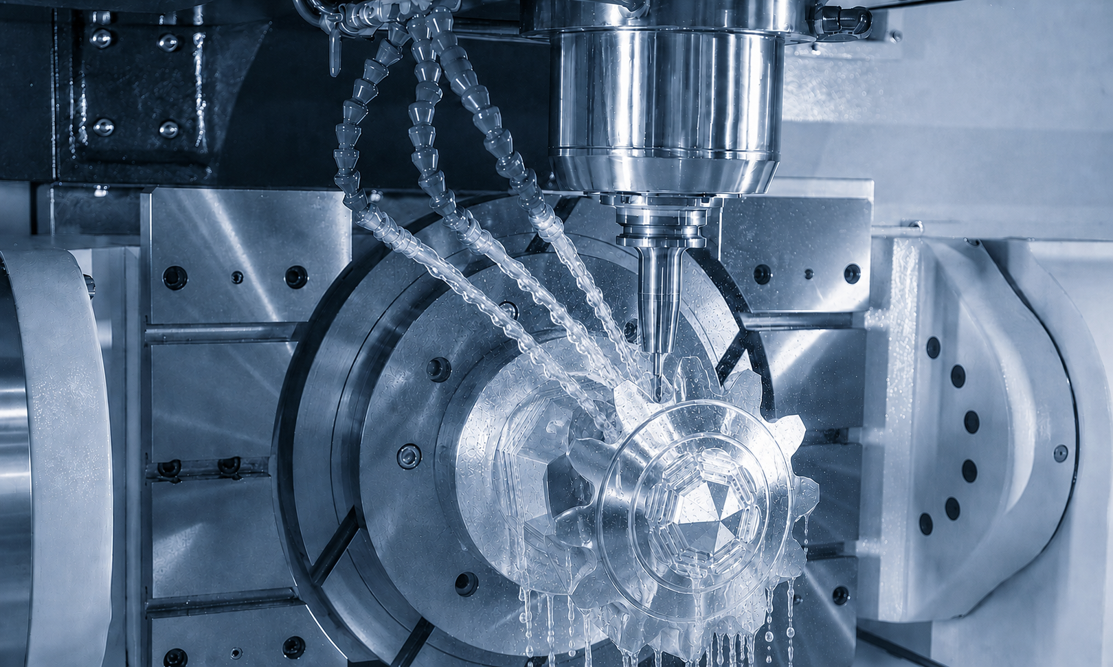
For procurement teams and engineers sourcing custom CNC machining services, understanding tolerances is not optional. It directly impacts part cost, lead time, assembly yield, and ultimately your product's reliability in the field. Yet tolerance specification remains one of the most misunderstood aspects of the sourcing process. Many drawings arrive with overly tight tolerances that drive up cost unnecessarily, while others lack critical callouts on functional features, leading to fit issues downstream.
This guide distills what our engineering team has learned over years of production — whether you are a seasoned mechanical engineer or a procurement manager reviewing a quote, you can make smarter decisions about tolerances.
What Exactly Is a CNC Machining Tolerance?
A tolerance defines the maximum permissible variation in a physical dimension. When a drawing calls out a hole diameter of 10.00 mm with a tolerance of ±0.05 mm, the finished hole can measure anywhere from 9.95 mm to 10.05 mm and still be accepted.
Tolerances exist because no manufacturing process can produce a part to an infinitely exact dimension. Even the most advanced 5-axis machining center has inherent variability — from tool deflection and thermal expansion to material spring-back and measurement uncertainty. The goal of tolerance specification is not to eliminate variation entirely (which is impossible) but to control it within limits that ensure proper function while keeping manufacturing economically viable.
There are several categories of tolerances you will encounter on a typical CNC machining drawing:
Linear tolerances — govern lengths, widths, heights, hole diameters, and other direct measurements.
Angular tolerances — control the allowable deviation of angles, such as a chamfer or a tapered surface.
Geometric tolerances (GD&T) — control form, orientation, location, and runout of features. Examples include flatness, parallelism, perpendicularity, concentricity, and position.
Surface finish — while not a dimensional tolerance per se, surface roughness (Ra) is often specified alongside tolerances and impacts both appearance and cost.
Understanding which features require tight control and which can rely on standard shop tolerances is the foundation of cost-effective precision part sourcing.
The Two Dominant Tolerance Standards: ISO 2768 vs. ASME Y14.5
When it comes to general tolerances on CNC machined parts, two standards dominate global manufacturing: ISO 2768 (used primarily in Europe, Asia, and the Middle East) and ASME Y14.5 (the North American standard for Geometric Dimensioning and Tolerancing).
ISO 2768: General Tolerances for the Rest of the Drawing
ISO 2768 is a general tolerance standard. It allows an engineer to place a single note in the drawing title block — such as "ISO 2768-mK" — and that note automatically sets default permissible variation for every dimension on the part that does not have an explicit tolerance callout. This dramatically simplifies drawing creation for non-critical features.
The standard is divided into two parts:
ISO 2768-1 covers general tolerances for linear and angular dimensions, with four precision classes: f (fine), m (medium), c (coarse), and v (very coarse).
ISO 2768-2 covers general tolerances for geometrical features — straightness, flatness, perpendicularity, symmetry, and runout — with three classes: H, K, and L.
A callout like "ISO 2768-mK" means medium-class linear tolerances (m) combined with K-class geometrical tolerances. This is one of the most commonly specified combinations in commercial and industrial CNC machining. As of 2026, the 1989 version of ISO 2768 remains the active standard, although a draft revision (ISO/DIS 2768) reached the DIS stage in 2025 with proposed changes including a restriction of scope to linear and angular sizes only. For now, the existing tables continue to govern most production.
ASME Y14.5: Full GD&T for Critical Assemblies
ASME Y14.5 is the dominant standard in North America and is increasingly required by US-based OEM supply chains. Unlike ISO 2768's "one note covers everything" approach, ASME Y14.5 provides a comprehensive symbolic language — Geometric Dimensioning and Tolerancing (GD&T) — that allows engineers to explicitly define the form, orientation, location, and runout of individual features using Feature Control Frames.
GD&T is more powerful but also more complex. It requires trained engineers to apply correctly and trained machinists and inspectors to interpret it. The payoff is that for complex assemblies with functional interfaces — think aerospace structural components, medical implant interfaces, or automotive transmission parts — GD&T removes ambiguity that general tolerances cannot.
Which Standard Should You Use?
| Aspect | ISO 2768 | ASME Y14.5 (GD&T) |
|---|---|---|
| Communication | Implied by a general note in the title block | Explicitly defined in Feature Control Frames |
| Best for | Non-critical parts, simple brackets, sheet metal | Complex assemblies, functional interfaces, precision parts |
| Geometric control | Limited to 5 characteristics | Full suite: position, profile, parallelism, cylindricity, and more |
| Drawing effort | Low — fast to create | Higher — requires trained GD&T engineers |
| Typical regions | Europe, Asia, Middle East | North America, US OEM supply chains |
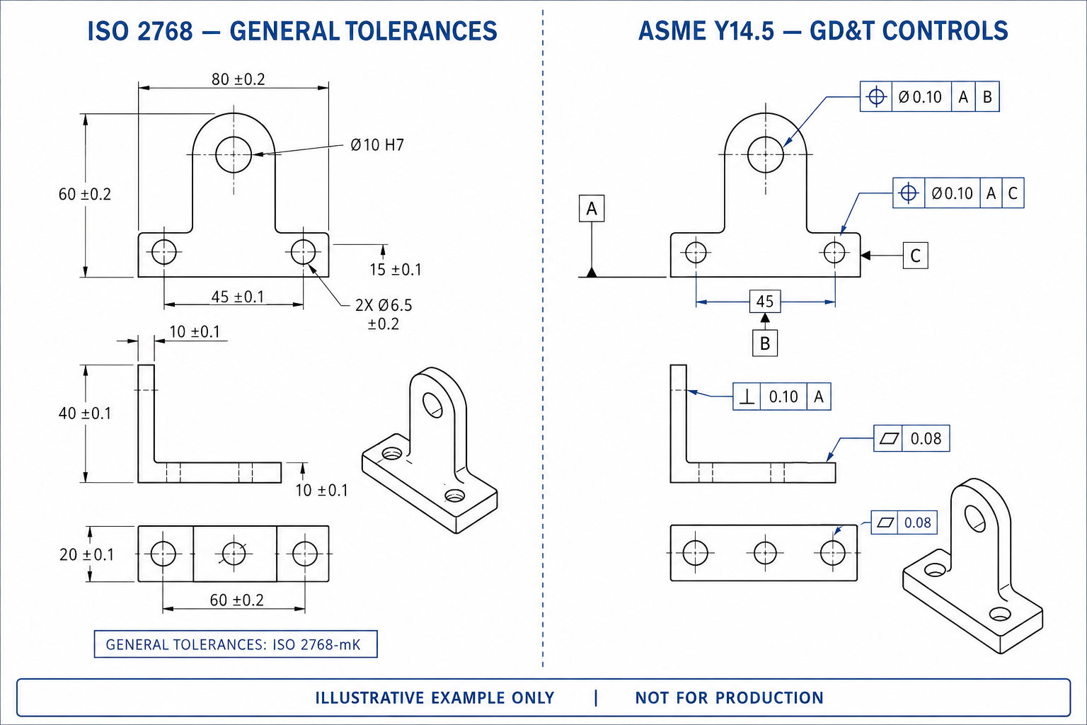
At Brightstar, our engineering team is fluent in both standards. We regularly produce parts to ISO 2768-mK for European customers, and to full ASME Y14.5 GD&T for US aerospace and medical clients. If your drawing uses one standard but your end customer expects the other, we can advise on the conversion — though we always recommend confirming with your design team before making changes.
Typical Tolerance Ranges by CNC Machining Process
Not all CNC machines are created equal, and the achievable tolerance depends heavily on the process used. Here is what you can realistically expect:
3-Axis CNC Milling
Standard 3-axis vertical machining centers are the workhorses of CNC machining. Depending on the part size, material, geometry, and setup, they can typically achieve:
General linear tolerances: ±0.10 mm to ±0.05 mm (±0.004" to ±0.002")
Tighter linear tolerances: ±0.025 mm to ±0.01 mm (±0.001" to ±0.0004"), achievable with careful fixturing and finishing passes
Hole-position tolerances: ±0.05 mm to ±0.025 mm, depending on the hole pattern, datum structure, and inspection method
3-axis machines are ideal for prismatic parts where all features are accessible from the top or from a limited number of setups. Every additional setup introduces potential stacking error, so parts requiring multiple re-fixturing operations tend to see wider tolerance accumulation.
5-Axis CNC Machining
5-axis machining centers rotate the part or tool in two additional axes, allowing complex geometries to be machined in a single setup. This single-setup advantage is critical for tolerance control:
General linear tolerances: ±0.025 mm to ±0.01 mm (±0.001" to ±0.0004")
High-precision capability: Down to ±0.005 mm (±0.0002") under controlled conditions, depending on part geometry, material, feature size, and inspection requirements
Feature-to-feature location tolerances: ±0.02 mm to ±0.01 mm for features machined in the same setup
Surface finish: Typically Ra 0.8-1.6 μm without secondary polishing
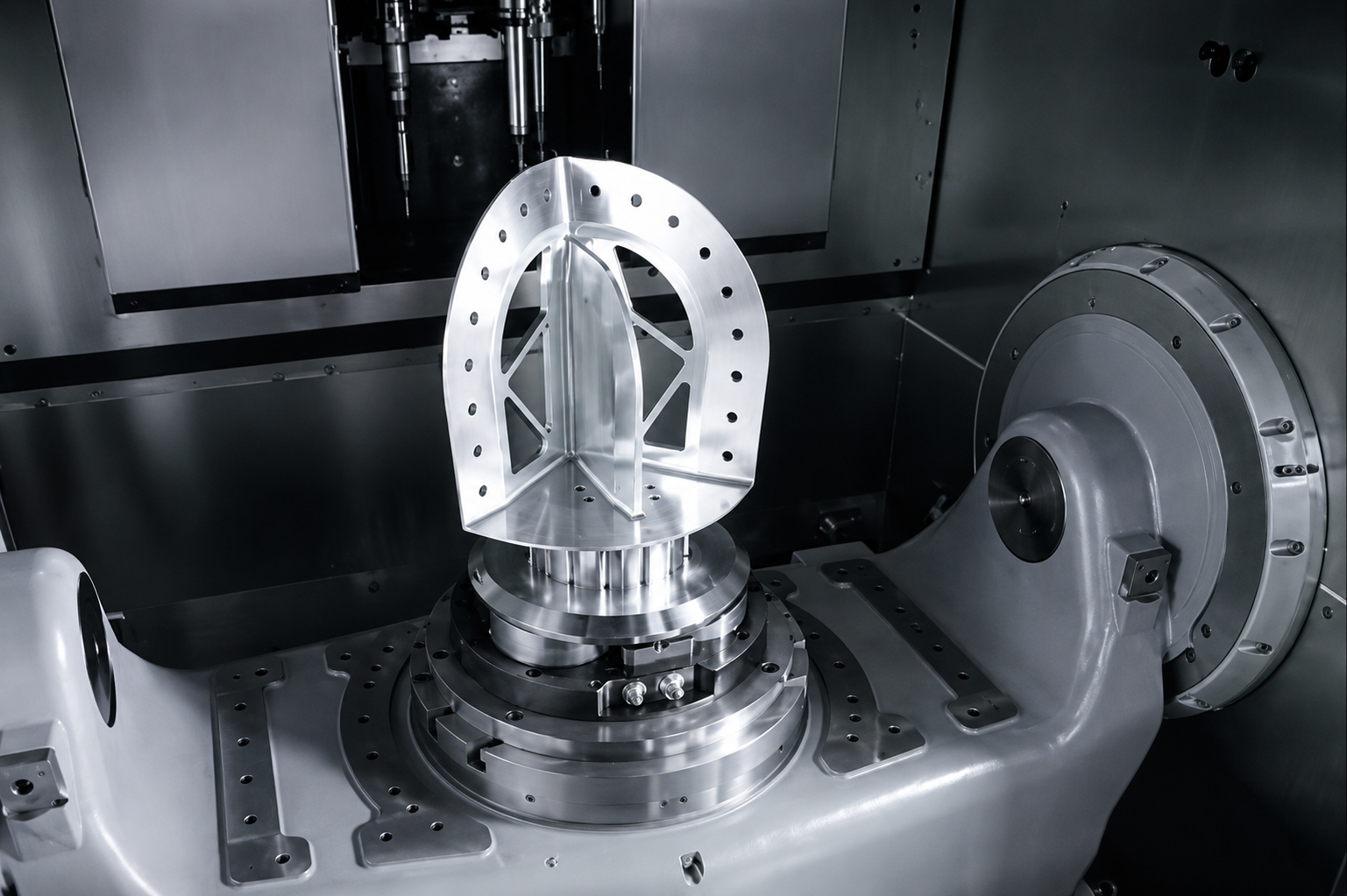
Because 5-axis machines reduce or eliminate multiple setups, they often deliver tighter overall tolerances on complex parts than 3-axis machines, even though the per-axis precision may be similar. This is why aerospace turbine components, medical implant bodies, and complex automotive connectors are increasingly produced on 5-axis equipment. At Brightstar, our fleet of over 70 machining centers includes both 3-axis and 5-axis machines. For parts with complex angled features or tight positional requirements, we will often recommend a 5-axis approach not because it is more expensive per hour, but because it reduces setup error and improves first-pass yield — which can actually lower total part cost.
CNC Turning (Lathe)
CNC turning produces rotational parts — shafts, bushings, connectors, valve bodies. Turning generally delivers excellent dimensional control:
Diameter tolerances: ±0.02 mm to ±0.005 mm (±0.0008" to ±0.0002"), depending on the material, diameter, length, and part geometry
Length tolerances: ±0.05 mm to ±0.02 mm
Total indicated runout (TIR): 0.01 mm to 0.005 mm between diameters turned in the same setup
Turned parts benefit from the rotational symmetry of the process, which naturally produces highly concentric features. When a part combines turned and milled features (done on a mill-turn or live-tool lathe), the tolerance at the interface between processes deserves special attention.
Grinding and Secondary Operations
When tolerances go below ±0.005 mm (±0.0002"), conventional CNC milling or turning typically cannot hold them consistently. At that point, secondary grinding operations — surface grinding, cylindrical grinding, or jig grinding — become necessary. Grinding can achieve:
Dimensional tolerances: ±0.0025 mm to ±0.001 mm (±0.0001" to ±0.00004"), depending on the material, feature size, and inspection method
Surface finish: Down to Ra 0.1 μm under controlled finishing conditions
Flatness: Down to 0.001 mm over a 100 mm surface
Grinding adds cost and lead time, so it should be reserved for features that genuinely require it — such as bearing journals, sealing surfaces, or precision gauge interfaces.
How Material Choice Affects Achievable Tolerances
The material you choose has a significant impact on the tolerances your CNC machined part can hold. Here is what our production floor experiences day in and day out:
Aluminum (6061, 7075, 5052)
Aluminum is the most common material in CNC machining for good reason. It machines quickly, produces excellent surface finishes, and holds tolerances well:
General tolerances: ±0.05 mm to ±0.025 mm
Tighter tolerances: ±0.01 mm to ±0.005 mm for suitable features under controlled machining and inspection conditions
Thermal consideration: Aluminum expands significantly with heat — approximately 23 μm/m/°C. During heavy machining, the part can grow measurably, then shrink as it cools. Experienced machinists account for this by taking finish passes at stable temperatures.
Aluminum parts are ideal for rapid prototyping, aerospace structural components, and consumer electronics enclosures. It is one of the materials with the highest daily processing volume.
Stainless Steel (304, 316, 17-4 PH)
Stainless steel is harder on tooling and generates more cutting heat, but it is dimensionally stable and holds excellent tolerances:
Standard tolerance: ±0.05 mm to ±0.025 mm
Tight capability: ±0.01 mm to ±0.005 mm with rigid fixturing and appropriate feeds/speeds
Work hardening: Austenitic stainless steels (304, 316) work-harden quickly, which can cause tool deflection and tolerance drift if machining parameters are not optimized.
Stainless steel is the material of choice for medical devices, food processing equipment, marine components, and any application requiring corrosion resistance. 17-4 PH stainless, in particular, is popular for aerospace and medical parts because it can be heat-treated to high strength after machining.
Titanium (Ti-6Al-4V)
Titanium offers an exceptional strength-to-weight ratio and biocompatibility, but it is one of the most challenging materials to machine:
Standard tolerance: ±0.1 mm to ±0.05 mm
Tight capability: ±0.025 mm to ±0.01 mm, but requires very rigid setups, sharp carbide tooling, and high-pressure coolant
Thermal conductivity: Titanium's low thermal conductivity means cutting heat stays in the tool rather than dissipating through the chip, accelerating tool wear and making consistent tolerance control more difficult.
Titanium is essential for aerospace structural components, medical implants, and high-performance automotive parts. The premium material cost and slower machining speeds mean that titanium parts are significantly more expensive than aluminum — but for applications where strength and weight matter, there is no substitute.
Engineering Plastics (PEEK, Delrin/Acetal, Nylon)
Plastics machine differently than metals and present unique tolerance challenges:
Standard tolerance: ±0.1 mm to ±0.05 mm
Tight capability: ±0.05 mm to ±0.025 mm, depending on the material
Thermal expansion: Plastics expand 5-10 times more than metals with temperature changes. A PEEK part machined at 25°C may shift by 0.05 mm or more if used at 80°C.
Moisture absorption: Nylon absorbs moisture from the air, causing dimensional growth over time.
PEEK is increasingly popular for medical and aerospace applications due to its high temperature resistance and biocompatibility. When designing plastic parts, always consider the end-use environment and specify tolerances that account for thermal and hygroscopic movement.
The Cost-Tolerance Relationship: Why Tighter Is Not Always Better
Here is the single most important economic principle in CNC machining: the relationship between tolerance and cost is not linear — it is exponential.
Many engineers and buyers assume that cutting a tolerance in half will roughly double the cost. In reality, tightening a tolerance beyond a certain threshold triggers a cascade of additional requirements that multiply cost far beyond what the precision is worth.
Industry data consistently shows the following pattern:
| Tolerance | Relative Cost Multiplier | Required Process & QC |
|---|---|---|
| ±0.1 mm (standard) | 1.0× (baseline) | Standard CNC machining, standard inspection |
| ±0.05 mm | 1.2-1.5× | Slower feed rates, additional finishing pass |
| ±0.025 mm (±0.001") | 2.5-3.5× | Precision finishing cuts, CMM verification |
| ±0.012 mm (±0.0005") | 4-5× | Climate-controlled workshop, dynamic tool balancing, 100% inspection |
| ±0.005 mm or tighter | 5-15× | Grinding required, dedicated metrology, high scrap risk |
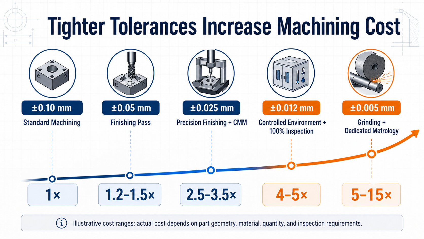
Why does cost escalate so dramatically behind tolerance tightening? Several factors come into play:
Slower machining parameters — Tight tolerances require lower feed rates and lighter depths of cut to minimize tool deflection. A part that takes 10 minutes at standard tolerances may take 30-45 minutes at tight tolerances.
Multiple finishing passes — Achieving ±0.01 mm typically requires a roughing pass, a semi-finishing pass, and a final finishing pass, each with its own tool change and setup time.
Specialized tooling — Tight tolerance work often requires high-precision collets, balanced tool holders, and premium carbide inserts that cost more and wear faster.
In-process inspection — The machinist must stop and measure features mid-cycle, adjusting offsets as needed. This adds significant non-cutting time.
Mandatory CMM inspection — Parts with tight tolerances cannot be reliably inspected with hand calipers. They require Coordinate Measuring Machine (CMM) verification, which adds inspection time and cost.
Higher scrap rate — Even with the best equipment and operators, tighter tolerances mean more parts fall outside the acceptable range. Scrap costs are baked into the quote.
Climate control — At tolerances below ±0.01 mm, ambient temperature variation in the factory becomes a significant factor. Temperature-controlled machining environments add overhead.
The practical takeaway: specify tight tolerances only on features that functionally require them. For all other dimensions, rely on the general tolerance standard noted in your title block. This one practice can reduce part cost by 20-40% on many components without any impact on performance.
How to Specify Tolerances Correctly on Your Drawings
A well-toleranced drawing is one of the most valuable documents in the sourcing process. It tells your CNC machining partner exactly what matters — and what does not. Here is a step-by-step approach:
Step 1: Identify Functional Features
Go through your part and ask: "Which features must fit, mate, seal, or move relative to another part?" These are your functional features, and they deserve explicit, tight tolerances. Examples include:
Bearing bores and shaft diameters (must achieve a specific clearance or interference fit)
Sealing surfaces (must be flat and smooth enough to prevent leakage)
Mounting hole patterns (must align with mating components)
Threaded interfaces (must assemble with standard fasteners)
Datum surfaces (used as reference for all other measurements)
Step 2: Apply General Tolerances to Everything Else
For all non-critical dimensions — overall lengths, non-mating edges, cosmetic features, reference dimensions — apply a general tolerance via your title block note (ISO 2768-mK or equivalent). This communicates your quality baseline without cluttering the drawing.
Step 3: Use GD&T for Positional and Geometric Requirements
For features where position, orientation, or form matters more than the individual dimension, use GD&T (ASME Y14.5) or the equivalent geometric tolerance callouts. For example, a bolt hole pattern is better controlled with a position tolerance relative to datums than with individual ±X/Y coordinate tolerances, because GD&T allows the pattern to shift as a whole within a cylindrical tolerance zone — which is usually what the assembly actually requires.
Step 4: Specify Surface Finish Where It Matters
Surface finish (Ra) affects friction, wear, sealing, and appearance. Specify Ra values on functional surfaces:
Ra 3.2 μm: Standard machined finish, suitable for most non-critical surfaces
Ra 1.6 μm: Good general-purpose finish, common for visible and mating surfaces
Ra 0.8 μm: Fine finish for sealing surfaces and bearing interfaces
Ra 0.4 μm or better: Precision finish requiring grinding or polishing
Step 5: Define Datums Clearly
Datums are the reference surfaces from which all other measurements are made. A drawing with unclear or inconsistent datums will produce parts that measure "in tolerance" individually but fail to assemble. Ensure that your primary, secondary, and tertiary datums are clearly marked and that they correspond to how the part will actually be fixtured and measured.
Step 6: Add a General Tolerance Note
A typical title block note might read:
"General tolerances per ISO 2768-mK unless otherwise specified. All dimensions in mm. Break all sharp edges 0.2 × 45°. Surface finish Ra 1.6 μm unless noted."
This single block of text communicates a tremendous amount of information to your machining partner and prevents costly back-and-forth during the quoting and production phases.
Common Tolerance Mistakes That Waste Money
Mistake 1: Applying Tight Tolerances to Every Dimension
This is by far the most common and most costly mistake. We regularly see drawings where every dimension — including non-functional edges and cosmetic features — is specified to ±0.01 mm or tighter. In many cases, the engineer applied a "default tight tolerance" out of caution or habit, without analyzing which features actually need it. Fix: Conduct a tolerance review before releasing the drawing. Tighten only functional features; let the rest fall under general tolerances. This single change can reduce quoted cost by 20-40%.
Mistake 2: Ignoring Tolerance Stack-Up
When multiple parts assemble together, individual tolerances accumulate (stack up) at the assembly level. A part that is perfectly within its own individual tolerances may still cause assembly issues if the cumulative variation exceeds the available clearance. Fix: Use tolerance stack-up analysis (worst-case or statistical) for critical assemblies. Consider using GD&T position tolerances, which often allow more generous individual feature tolerances while maintaining assembly functionality.
Mistake 3: Specifying Tolerances Tighter Than the Process Can Hold
Some drawings call out ±0.002 mm on a milled aluminum surface — a tolerance that requires grinding, not milling. The result is either a much more expensive part (if the shop adds grinding) or a part that fails inspection (if they try to mill it). Fix: Understand the realistic capability of each manufacturing process. If you need sub-0.005 mm tolerance, plan for grinding from the start and budget accordingly.
Mistake 4: Inconsistent Datum References
A drawing that references Datum A on one view and a different surface labeled Datum A on another view creates confusion. Machinists and inspectors may interpret the drawing differently, leading to inconsistent results. Fix: Ensure datums are consistently labeled across all views. Use datum target symbols where a full surface datum is not practical.
Mistake 5: Omitting Surface Finish Specifications
A part with perfect dimensional tolerances but an unspecified surface finish may arrive with a rough, tool-marked surface that is unsuitable for sealing, sliding, or cosmetic purposes. Fix: Specify a default surface finish in your title block (e.g., Ra 1.6 μm) and call out tighter finishes on specific functional surfaces.
Mistake 6: Not Accounting for Material-Specific Behavior
A tolerance that is straightforward in aluminum may be difficult to hold in titanium due to tool deflection, or in plastic due to thermal expansion. Specifying the same tolerance across all materials without adjustment leads to either unnecessary cost or unachievable requirements. Fix: Adjust tolerance expectations based on material. Our team can advise on realistic tolerances for your chosen material during the quoting phase.
Tolerance Best Practices by Industry
Tolerance requirements vary by industry. Aerospace parts may require ±0.05 mm to ±0.025 mm for general features and down to ±0.005 mm for critical engine components, together with material traceability, FAI, and CMM inspection. Medical components often require ±0.025 mm to ±0.005 mm on functional features, with additional surface finish, biocompatibility, and process documentation requirements. Automotive tolerances typically range from ±0.2 mm for cosmetic parts to ±0.01 mm for critical engine and transmission features, with PPAP and consistent process control required for series production. For those requirements, Brightstar's ISO 9001:2015 quality system supports documented inspection and traceability according to each project's requirements.
Brightstar Delivers Precision Parts Consistently
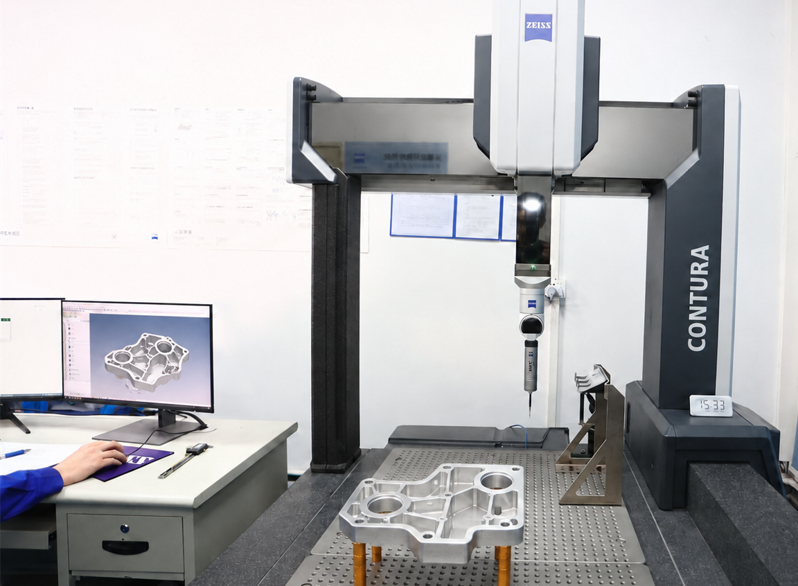
At Brightstar, consistent tolerance control depends on the entire manufacturing system, not only the machine specification. Our Dongguan facility operates more than 70 well-maintained 3-axis, 4-axis, and 5-axis CNC machines, supported by regular calibration, preventive maintenance, and scheduled spindle accuracy checks. Our experienced machinists and programmers select suitable tooling, cutting parameters, machining strategies, and fixturing based on each part's material, geometry, and tolerance requirements. By combining reliable equipment with practical manufacturing experience, we consistently produce precision parts that meet customer drawings and inspection requirements. If you are unsure how to specify the right tolerance for a particular feature, our engineering team can help. Contact us or upload your drawings and 3D models directly for a cost-effective precision machining solution.

Disclaimer
All quantitative data (percentages and hourly rates) provided in this article are for illustrative and educational purposes only, based on industry averages. Actual costs may vary depending on specific part geometry, fluctuations in raw material market prices, and regional labor rates. For accurate project costing, Brightstar Prototype CNC Co., Ltd recommends contacting our team directly for current quotes tailored to your specific requirements.