
CNC Turning vs CNC Milling: Which Process Is Right for Your Parts?

When you send a part drawing to a precision CNC Machining supplier, one of the first decisions the engineering team makes is whether to route your part to a CNC lathe (turning) or a CNC milling center — or both. For many buyers and product designers, the distinction between these two foundational CNC processes can feel unclear. You might know that turning makes round parts and milling makes everything else, but the reality is more nuanced — and choosing the right process (or combination) directly impacts your part cost, lead time, dimensional accuracy, and even design feasibility.
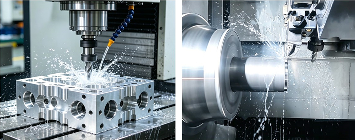
At Brightstar, we operate more than 70 precision CNC Machining centers across our Dongguan facility, including both CNC lathes (with live tooling and Y-axis capability) and 3-axis to 5-axis CNC milling centers. Every month, our process engineers evaluate thousands of part drawings and decide the optimal manufacturing route. This guide distills that shop-floor experience into a practical framework you can use to understand which process your part needs, how to design for each one, and how to avoid common mistakes that drive up cost.
Whether you're sourcing precision shafts, hydraulic components, medical device housings, aerospace brackets, or automotive transmission parts, understanding the turning-versus-milling decision will help you communicate better with suppliers, design more manufacturable parts, and reduce overall production cost.
What Is CNC Turning?
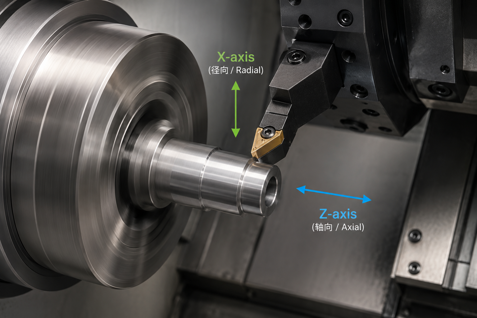
CNC turning is a machining process where the workpiece rotates at high speed while a single-point cutting tool moves along the surface to remove material. The part is held in a chuck (usually a 3-jaw or collet chuck) mounted on the lathe's spindle, and the cutting tool is fed in two linear directions:
X-axis — moving toward or away from the center of the rotating part (controls diameter)
Z-axis — moving along the length of the part (controls length and facing)
Because the workpiece rotates, turning naturally produces axisymmetric (round) geometries — cylinders, cones, spheres, threads, grooves, and tapered profiles.
Common turning operations
Facing — machining the end face of a part flat and perpendicular to the axis
OD (outer diameter) turning — reducing the diameter of a cylindrical part
ID (inner diameter) boring — enlarging and finishing an existing hole
Drilling / tapping — creating holes along the central axis (on lathes with live tooling)
Threading — cutting external or internal screw threads
Grooving / parting — cutting narrow recesses or separating a finished part from the stock
Knurling — creating a textured grip pattern on a cylindrical surface
Modern CNC lathe capabilities
Today's CNC lathes are far more capable than simple two-axis turning machines. Many are equipped with:
Live tooling (driven tools) — rotating tools that can drill, mill, and tap features perpendicular to the part axis, eliminating the need for a secondary milling operation
Y-axis — allows off-center milling and drilling, further expanding what a lathe can do in one setup
Sub-spindle — a second spindle that picks up the part and machines the back side without manual re-fixturing
Bar feeder — automatically feeds raw bar stock for high-volume production runs
These advanced lathes, often called turn-mill centers or mill-turn machines, blur the line between turning and milling. We'll discuss that hybrid capability later in this article.
What Is CNC Milling?
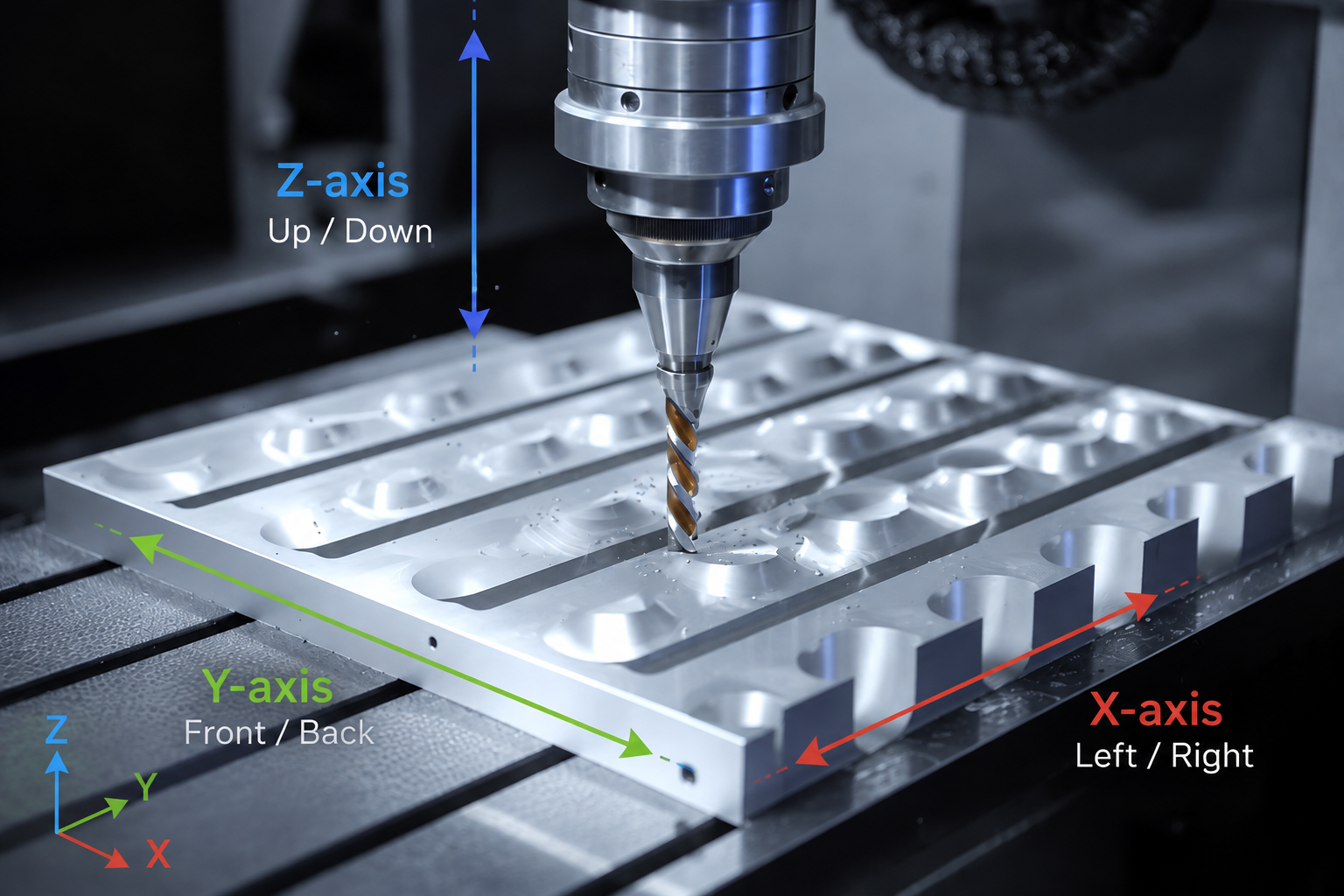
CNC milling is a machining process where a rotating multi-point cutting tool moves along multiple axes to remove material from a stationary workpiece. The part is typically clamped in a vise, fixture, or on a rotary table, while the cutting tool (end mill, face mill, drill, tap, etc.) moves along three or more axes:
X-axis — left to right
Y-axis — front to back
Z-axis — up and down (the tool plunges into and retracts from the part)
On 3-axis milling machines, the cutting tool moves along the X, Y, and Z linear axes. On 4-axis and 5-axis milling machines, additional rotary axes allow the tool or workpiece to rotate or tilt, enabling the machining of more complex 3D geometries, angled surfaces, and compound-angle features.
Common milling operations
Face milling — machining a large flat surface to a precise depth
End milling / profiling — cutting slots, pockets, and contoured shapes
Drilling — creating holes at specific locations
Tapping — creating internal threads
Boring — enlarging and finishing holes to tight tolerances
Chamfering / deburring — breaking sharp edges
3D surfacing — machining complex curved surfaces (mold cavities, turbine blades, organic shapes)
Engraving — cutting text or logos into a part surface
Milling machine types
3-axis vertical milling center (VMC) — the most common type, tool moves in X/Y/Z, part stays flat. Best for prismatic parts with features on the top and sides.
4-axis milling — adds a rotary axis (A-axis) to rotate the part, allowing access to multiple sides in one setup. Good for parts with circumferential features.
5-axis milling — adds two rotary axes, allowing the tool to approach the part from virtually any angle. Required for complex 3D contours and undercuts.
Horizontal machining center (HMC) — spindle is horizontal, part sits on a rotary tombstone. Better for high-volume production and deep chip evacuation.
Key Differences: Turning vs Milling at a Glance
| Feature | CNC Turning | CNC Milling |
|---|---|---|
| What rotates | The workpiece | The cutting tool |
| Natural geometry | Round / axisymmetric parts | Prismatic, flat, complex 3D parts |
| Typical axes | 2 axes (X, Z), plus live tooling | 3-5 axes (X, Y, Z + rotary) |
| Workholding | Chuck, collet, between centers | Vise, custom fixture, tombstone |
| Best for | Motor shafts, hydraulic pins, bushings, threaded fasteners, valve stems | Aluminum housings, mounting brackets, electronic enclosures, molds, robotic components |
| Cycle time for simple parts | Very fast (single continuous cut) | Slower (multiple tool passes) |
| Setup complexity | Low for simple round parts | Higher for complex fixturing |
| Material removal rate | High for round stock | High for block/plate stock |
| Minimum feature size | Limited by tool boring diameter | Limited by smallest end mill diameter |
| Typical tolerance | ±0.005 mm to ±0.05 mm | ±0.01 mm to ±0.05 mm |
| Typical Example | Stainless steel shaft part (Ø32 × 120 mm) | 6061 aluminum housing with pockets and side holes |
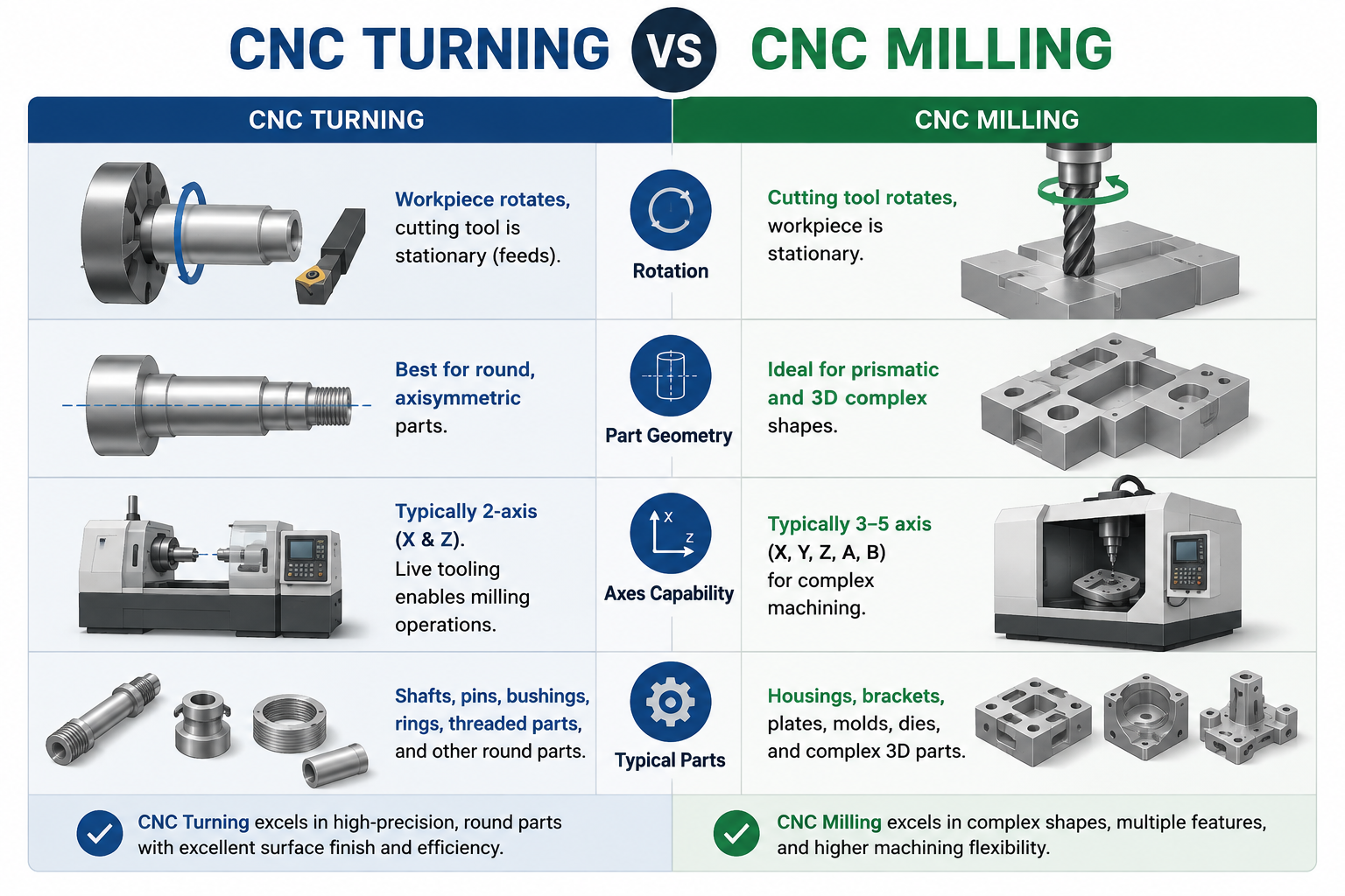
Real-world example: A stainless-steel motor shaft is typically produced by CNC turning because of its rotational symmetry, while a 6061 aluminum equipment housing with pockets and side holes is better suited to 5-axis CNC milling.
When to Choose CNC Turning
CNC turning is the optimal process when your part meets one or more of the following criteria:
1. The part is primarily cylindrical or axisymmetric
If your part's dominant feature is a round cross-section — a shaft, pin, bushing, sleeve, collar, roller, or connector body — turning is almost always the most efficient and cost-effective process. A CNC lathe can produce the entire outer profile in a single continuous cut, whereas a milling machine would need many circular interpolation passes to approximate the same round shape.
Typical turned parts: motor shafts, hydraulic valve spools, bearing sleeves, threaded fasteners, pipe fittings, drill bit bodies, pen barrels, camera lens rings.
2. You need precise concentricity between features
Turning produces features that are inherently concentric with the part's rotational axis. If your design requires tight runout tolerance between an outer diameter and an inner bore (common in bearings, hydraulic cylinders, and rotary components), turning both features in the same setup ensures near-perfect concentricity. Achieving the same concentricity on a milling machine would require expensive custom fixturing and multiple alignments.
3. The part requires internal threads or deep bores
CNC lathes excel at boring deep, precise internal holes and cutting internal threads. The single-point boring tool can achieve excellent surface finish and tight diameter control inside a bore, which is difficult to match with milling.
4. High-volume production of round parts
For quantities above 100 pieces of a round part, a CNC lathe with a bar feeder can run unattended for hours, producing parts at a very low per-unit cost. The cycle time for a typical turned part is often 1-3 minutes, compared to 10-30 minutes for an equivalent milled part.
5. The part has a high length-to-diameter ratio
Long, slender parts (shafts, rods, spindles) are naturally suited to turning, where the part is supported between centers or in a steady rest. Milling a long slender part would require extensive fixturing to prevent deflection and chatter.
When to Choose CNC Milling Services
CNC milling is the right choice when your part has characteristics that turning cannot efficiently produce:
1. The part has a non-round, prismatic shape
If your part is fundamentally a block, plate, bracket, housing, or frame with flat faces, square corners, and irregular profiles, milling is the only practical option. Turning cannot create flat external surfaces or square profiles efficiently.
Typical milled parts: equipment housings, mounting brackets, manifold blocks, mold cavities, gearbox bodies, electronic enclosures, robot structural components.
2. The part has features on multiple faces or sides
A milling machine (especially 4-axis or 5-axis) can access features on the top, bottom, and all four sides of a part in one or two setups. While a lathe with live tooling can add some cross-holes and flats, it cannot efficiently machine complex features on multiple non-rotational faces.
3. The part requires 3D contoured surfaces
Any part with organic curves, sculpted surfaces, undercuts, or compound angles — such as turbine blades, impellers, mold cavities, prosthetic implants, or ergonomic handles — requires milling (usually 5-axis simultaneous milling). Turning is limited to axisymmetric profiles.
4. The part has pockets, slots, and irregular internal features
Milling is far more efficient for creating rectangular pockets, T-slots, dovetails, keyways, and other non-circular internal features. While a lathe with live tooling can mill a simple keyway, complex internal geometry is the domain of milling.
5. The raw material is plate or block stock
If your part is cut from a flat plate or rectangular block (aluminum plate, steel block, plastic sheet), milling is the natural starting point. Turning requires round bar or tube stock.
6. Low-volume prototypes with complex geometry
For one-off or low-volume prototype parts with complex geometry, a 3-axis or 5-axis milling center offers the most flexibility. You can machine virtually any shape from a solid block without needing custom turning fixtures or special bar stock.
Parts That Need Both: Turn-Mill Combined Machining
Many real-world parts don't fit neatly into "turning only" or "milling only." A common example is a hydraulic valve body: it starts as a round bar turned to the correct outer diameter and internal bore, then requires cross-drilled holes, mounting flats, and threaded ports on the sides — features that need milling.
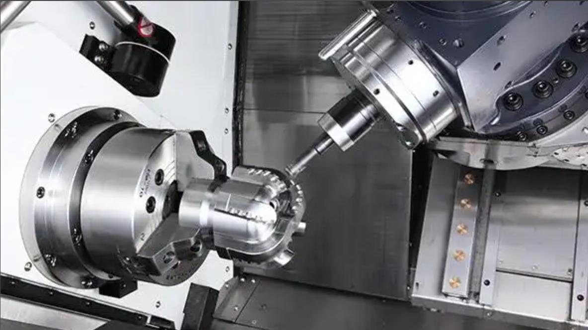
There are two ways to handle these parts:
Option 1: Separate operations (turn, then mill)
The part is first fully machined on a CNC lathe, then transferred to a CNC milling center for the secondary operations. This is cost-effective for low-volume parts when you already have both machine types available. The downside is that each transfer introduces a small alignment error and adds setup labor.
Option 2: Turn-mill center (one setup)
A turn-mill center (also called a mill-turn machine) combines a CNC lathe with live tooling, a Y-axis, and sometimes a B-axis milling spindle. This allows both turning and milling operations in a single setup, eliminating alignment errors and reducing lead time. At Brightstar, we use turn-mill centers for complex rotational parts that require cross-holes, flats, keyways, or even helical grooves — all completed in one clamping.
Parts that benefit from turn-mill combined machining:
• Hydraulic valve bodies with cross-ports and mounting flats
• Aerospace fittings with threaded ends and flange bolt holes
• Medical instrument handles with ergonomic milled grip features
• Automotive transmission shafts with keyways and cross-drilled oil holes
• Custom fasteners with non-round head features
If your part has a predominantly round shape but also requires some milled features, ask your supplier whether a turn-mill center can handle it in one setup — it often saves both time and cost compared to running the part on two separate machines.
Cost Comparison: Turning vs Milling
CNC Turning vs CNC Milling: Which Is More Cost-Effective?
One of the most common questions engineers ask is: Is CNC turning cheaper than CNC milling? In general, CNC turning is more cost-effective for rotationally symmetric parts because material removal is continuous and cycle times are shorter. However, for prismatic components with multiple faces, pockets, and holes, CNC milling is often the more efficient manufacturing solution.
Machine hourly rates (indicative)
| Machine Type | Typical Hourly Rate (USD) | Best For |
|---|---|---|
| 2-axis CNC lathe | $25 – $45 | Simple round parts, high volume |
| CNC lathe with live tooling | $40 – $65 | Round parts with cross-holes, flats, keyways |
| Turn-mill center (Y-axis + sub-spindle) | $60 – $100 | Complex rotational parts, one-setup machining |
| 3-axis vertical milling center | $35 – $60 | Prismatic parts, 2.5D features |
| 4-axis milling center | $50 – $80 | Multi-sided parts, simple rotary features |
| 5-axis milling center | $80 – $150+ | Complex 3D contours, compound angles |
Why turning is often cheaper for round parts
For a simple cylindrical part, turning is almost always less expensive than milling for three reasons:
Faster material removal: A turning tool cuts continuously along the rotating surface, removing material much faster than a milling tool's interrupted cuts.
Fewer tool changes: A typical turned part needs 3-5 tools (facing tool, roughing tool, finishing tool, drill, tap). A milled part of similar complexity may need 8-15 tools.
Simpler fixturing: A standard 3-jaw chuck or collet works for most turned parts. Milled parts often require custom fixtures, soft jaws, or tombstone setups.
When milling becomes cost-competitive
For parts with complex geometry that would require multiple turning setups and custom fixtures, a single milling setup can be more cost-effective despite the higher hourly rate. The key is to look at total part cost, not just the machine rate.
Material Considerations
Both turning and milling can process virtually any machinable material, but each process has material-specific considerations:
Materials that turn exceptionally well
Aluminum alloys (6061, 7075, 2024): Excellent chip formation, high surface speeds, very low tool wear. Turning aluminum is extremely fast and cost-effective.
Brass and copper: Free-machining brasses (C36000) produce short chips and excellent surface finish. Copper is softer and requires sharp tools to avoid smearing.
Mild steel (1018, 12L14): Good machinability, especially leaded steels like 12L14 which are specifically formulated for turning.
Stainless steel (303, 304, 316): 303 is free-machining; 304 and 316 require lower speeds and more rigid setups due to work hardening.
Titanium (Ti-6Al-4V): Difficult to machine due to low thermal conductivity. Requires rigid lathes, sharp tools, and generous coolant. Turning titanium is generally more efficient than milling because the continuous cut generates less heat per unit volume.
Materials that mill exceptionally well
Aluminum plate: The most common milling material. High speeds and feeds produce excellent surface finish.
Tool steel (P20, H13, S7): Commonly milled for mold and die applications. Requires rigid machines and appropriate tooling (carbide or ceramic).
Engineering plastics (PEEK, Delrin, nylon, PC): Mill well with sharp tools and appropriate speeds. Thin walls and fine details are more easily achieved by milling than turning.
Stainless steel plate: Milling stainless requires rigid fixturing and climb milling to avoid work hardening.
Material form factor matters
The form of your raw material often dictates the starting process:
Round bar stock → start with turning (you can always add milling operations later)
Rectangular plate/block → start with milling
Tube stock → turning for OD/ID, then milling for side features
Cast or forged blank → milling is usually the primary process
Tolerance and Surface Finish Capabilities
Both processes can achieve high precision, but their natural strengths differ:
Turning tolerances
Diameter tolerance: ±0.005 mm to ±0.02 mm is routinely achievable on a well-maintained CNC lathe with a sharp insert.
Length tolerance: ±0.02 mm to ±0.05 mm, depending on part length and thermal expansion.
Concentricity / runout: 0.005 mm to 0.01 mm TIR (total indicator reading) when features are turned in the same setup.
Surface finish: Ra 0.4 μm to Ra 1.6 μm with a standard finishing insert. Ra 0.1 μm possible with polishing inserts or burnishing.
Milling tolerances
Linear dimension tolerance: ±0.01 mm to ±0.05 mm on a 3-axis machine. ±0.005 mm possible on high-precision 5-axis machines with careful process control.
Position tolerance (holes): ±0.01 mm to ±0.02 mm with a well-calibrated machine and proper fixturing.
Flatness: 0.005 mm to 0.02 mm over 100 mm, depending on machine rigidity and part material.
Surface finish: Ra 0.8 μm to Ra 3.2 μm with standard end mills. Ra 0.4 μm possible with high-speed finishing and sharp tools. Curved 3D surfaces may show step marks that require hand polishing.
Key takeaway
If your part's most critical tolerance is a diameter or concentricity specification, turning is inherently more accurate. If the critical tolerance is a flatness, position, or 3D profile specification, milling (especially 5-axis) is the better choice.
Design Tips for Each Process
Design tips for CNC turning
Avoid undercuts that require special form tools. Standard turning inserts have limited reach and profile capability. Deep internal undercuts require custom boring bars that add cost.
Specify a standard radius on corners and edges. Sharp internal corners require a sharp-nosed insert that is fragile and leaves a poor finish. A 0.5 mm or 1 mm radius is standard and cost-effective.
Keep length-to-diameter ratio under 4:1 for boring. Deep, narrow bores cause tool deflection and chatter. If you need a deep bore, consider using a gun drill or reaming operation.
Allow enough material for gripping. When designing a part that will be turned from bar stock, leave at least 2-3 mm of extra length for the chuck to grip, plus a parting-off allowance.
Use standard thread sizes. Custom thread pitches require special inserts and increase cost. Metric (M) and unified (UNC/UNF) standard threads are most economical.
Avoid thin-walled sections. Turning thin-walled parts causes chatter and dimensional instability. If a thin wall is necessary, specify a minimum wall thickness of 1.5× the wall height.
Design tips for CNC milling
Use internal corner radii equal to or larger than the tool radius. A sharp internal corner (R0) is impossible to mill — the smallest end mill leaves a radius. Specify R0.5 mm or R1 mm to avoid tiny, expensive tools.
Keep pocket depth-to-width ratio under 4:1. Deep, narrow pockets require long end mills that deflect and chatter. If you need a deep pocket, consider a stepped design.
Avoid thin walls and thin floors. Minimum recommended wall thickness is 0.8 mm for aluminum, 1.0 mm for steel, and 1.5 mm for stainless steel. Thinner walls risk deformation during machining.
Specify standard hole sizes. Use standard drill diameters (e.g., 3.0 mm, 4.0 mm, 5.0 mm) rather than custom sizes (e.g., 3.37 mm). Custom hole sizes require reaming or interpolation, adding cost.
Minimize the number of setups. Design features so they can be accessed from the top and one side if possible. Every additional side requires a new setup and adds cost.
Add chamfers to all external edges. Chamfers (0.3 mm to 1 mm) are faster to machine than radii and eliminate sharp burrs. Specify "break all sharp edges 0.3 × 45°" as a default.
Need Help Choosing the Right Process?
At Bright Rapid, our process engineers evaluate every RFQ based on part geometry, setup requirements, tooling feasibility, tolerance requirements, and overall manufacturing cost. Whether a component is best produced by CNC turning, milling, or a combination of both, our goal is to identify the most efficient and cost-effective manufacturing route.
With 70+ CNC machines, including turning centers, turn-mill machines, and 3-axis to 5-axis machining centers, we are not limited to a single process. We select the manufacturing method that best matches your design requirements.
If you're unsure which process is right for your part, send us your CAD file for a free manufacturability review and quotation. Our engineering team will recommend the optimal machining strategy based on your geometry, tolerance, quantity, and budget requirements.
Common Misconceptions
Misconception 1: "Turning is only for simple round parts"
Modern CNC lathes with live tooling, Y-axis, and sub-spindles can produce surprisingly complex parts — including cross-drilled holes, milled flats, keyways, helical grooves, and even gear teeth. Many parts that buyers assume require milling can be completed more efficiently on a turn-mill center.
Misconception 2: "Milling is more accurate than turning"
Not necessarily. For diameter and concentricity specifications, turning is inherently more accurate because the part rotates around a fixed axis. A well-maintained CNC lathe can hold ±0.005 mm diameter tolerances routinely. Milling accuracy depends more on machine rigidity, tool deflection, and fixturing precision.
Misconception 3: "If a part has any flat surface, it needs milling"
A CNC lathe with live tooling can mill flats, keyways, and even hexagonal profiles on a round part. If the flat features are simple and the part is predominantly round, a live-tooling lathe is often more efficient than transferring the part to a milling machine.
Misconception 4: "Turn-mill centers are always the best choice"
While turn-mill centers offer great flexibility, they have higher hourly rates and smaller work envelopes than dedicated machines. For simple round parts, a standard 2-axis lathe is more economical. For large, complex prismatic parts, a dedicated 5-axis milling center is the better choice. Turn-mill centers shine for medium-complexity rotational parts that would otherwise require two setups on separate machines.
Misconception 5: "The process doesn't matter as long as the part meets the drawing"
The manufacturing process directly affects cost, lead time, surface finish, and even the internal stress state of the part. A part that is milled from a solid block may have different residual stress characteristics than the same geometry turned from bar stock — which can matter for high-precision or high-stress applications. Always discuss the process route with your supplier, especially for critical components.
Questions to Ask Your Machining Supplier
When evaluating quotes and capabilities, ask your supplier these questions:
Which process are you proposing for my part, and why? A good supplier will explain the routing logic, not just give you a price.
Can this part be made on a turn-mill center to reduce setups? If your part is round with milled features, this is always worth asking.
What is the expected cycle time and total part cost? Compare total landed cost, not just hourly rates.
Are there design changes that would allow a simpler (cheaper) process? A proactive supplier will suggest DFM improvements that could move your part from a 5-axis mill to a 3-axis mill or from a turn-mill center to a standard lathe.
What are the achievable tolerances and surface finishes for the proposed process? Make sure they match your drawing requirements before you place the order.
Do you have both turning and milling capability in-house? If a supplier only has milling machines, they may sub-contract turning operations, adding cost and lead time. Brightstar handles both processes under one roof.
Conclusion
The CNC turning vs. CNC milling decision is not about which process is "better" — it's about matching the process to your part's geometry, tolerances, volume, and cost targets.
Choose CNC turning when: your part is predominantly cylindrical or axisymmetric, requires tight concentricity, has deep bores or internal threads, or is a high-volume round component. Turning offers faster cycle times, lower per-unit cost, and superior diameter/concentricity accuracy for round parts.
Choose CNC milling when: your part has a prismatic or complex 3D shape, features on multiple faces, pockets and slots, organic contoured surfaces, or is made from plate/block stock. Milling offers unmatched geometric flexibility and is the only practical option for non-round parts.
Choose turn-mill combined machining when: your part is predominantly round but also requires cross-holes, flats, keyways, or other milled features. Completing both operations in one setup reduces alignment errors, cuts lead time, and often lowers total cost.
The most important advice we can give is to involve your machining supplier early in the design process. A 10-minute DFM review can reveal whether your part should be turned, milled, or both — and the answer can save you thousands of dollars and weeks of lead time. At Brightstar, we welcome early-stage design consultations. Send us your 3D model and drawing, and our engineering team will recommend the optimal process route with a detailed quotation.
Disclaimer
All quantitative data (percentages and hourly rates) provided in this article are for illustrative and educational purposes only, based on industry averages. Actual costs may vary depending on specific part geometry, fluctuations in raw material market prices, and regional labor rates. For accurate project costing, Brightstar Prototype CNC Co., Ltd recommends contacting our team directly for current quotes tailored to your specific requirements.
Sources
Machining Data Handbook, Technomar Publishing. Reference for turning and milling parameters, tooling recommendations, and material machinability ratings.
Society of Manufacturing Engineers (SME), Fundamentals of Metal Machining. Industry guidance on CNC turning and milling process‑selection principles.
Modern Machine Shop, "Turn‑Mill Centers: Combining Operations for Efficiency", technical industry analysis.
ISO 2768‑1:1989, General tolerances — Part 1: Tolerances for linear and angular dimensions without individual tolerance indications, reference for general‑purpose machining tolerances.