
Aluminum CNC Machining: When Do Custom Parts Require 5-Axis Machining?

An engineering and sourcing guide for custom aluminum parts
During drawing review and quotation for aluminum CNC machining projects at Brightstar Prototype CNC Co., Ltd., one question appears repeatedly: does this part genuinely require 5-axis machining? Some parts look complex but contain critical features in only a few fixed orientations, making 3-axis or 3+2 machining a reliable option. Others appear straightforward but include multi-directional hole patterns, deep cavities, thin walls, or blended surfaces that make repeated repositioning risky.
Five-axis machining is therefore not automatically the best process, and machine-hour rate is not the right measure on its own. The practical decision depends on tool access, tolerance relationships, setup count, surface requirements, material stability, and the total cost of conforming parts.
What This Article Will Help You Decide
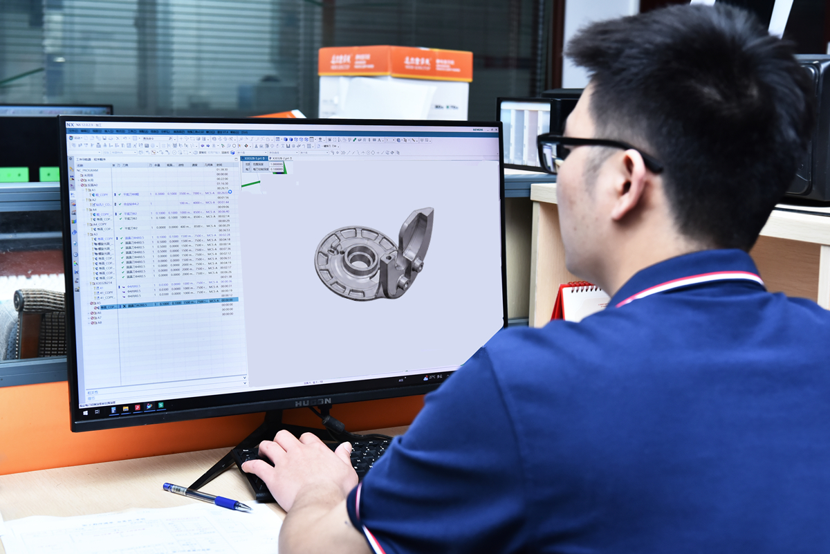
This guide explains how engineers, R&D teams, and purchasing engineers can choose among 3-axis machining, 3+2 positional machining, and simultaneous 5-axis machining. It connects design, accessibility, datums, alloy and temper, distortion, finishing, inspection, and purchasing cost, and concludes with a DFM and RFQ checklist.
1. Three Common Misunderstandings About 5-Axis Machining
Misunderstanding 1: A Complex Appearance Proves That 5-Axis Is Required
A visually complex part may not require simultaneous 5-axis motion. If all critical features are accessible from a limited number of fixed orientations and repositioning does not compromise functional tolerances, 3-axis or 3+2 machining may be more economical. Conversely, a simple-looking enclosure may have holes on five faces that must all relate to one mounting datum. Tool access and datum relationships matter more than appearance.
Misunderstanding 2: Reviewing Individual Tolerances Without the Datum Relationships
The route is often determined not by one tight size tolerance, but by the relationship among holes, planes, sealing faces, and profiles. True position across several directions, parallelism between mounting and sealing faces, or profile relative to a multi-face datum system can all be affected by repositioning. Five-axis machining can shorten the datum chain, but it cannot correct an ambiguous drawing.
Misunderstanding 3: Selecting 5-Axis Only to Reduce Setups
Fewer setups are valuable, but they are not sufficient justification. If a stable 3-axis fixture or 3+2 process can meet the requirements, simultaneous 5-axis may add programming, simulation, and collision-checking effort without a corresponding quality benefit. Compare setup count, risk, lead time, and total batch cost.
2. Four Engineering Tests for Deciding Whether 5-Axis Is Needed
1. Can the Tool Reach Every Critical Feature From a Practical Direction?
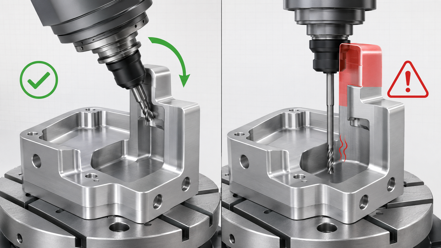
Deep cavities, angled holes, features beside tall walls, small internal radii, and local undercuts can force excessive tool overhang. As overhang increases, rigidity falls and vibration, deflection, dimensional drift, and inconsistent cutter marks become more likely. Five-axis motion can tilt the tool or workpiece so that a shorter cutter approaches from a better direction. It does not make every feature reachable; design changes, revised workholding, EDM, or a separate operation may still be required.
2. Do Critical Tolerances Cross Several Machining Directions?
When related critical features are completed in one primary setup, they can share a shorter and more stable datum chain. This is particularly important for multi-directional hole patterns, profiles spanning several faces, and position relative to a mounting surface. A 5-axis machine may still require a second setup for a clamping face or an area blocked by the fixture, so "one setup" should not be assumed without reviewing the workholding plan.
3. Must the Surface Be Machined Continuously?
Splitting a cosmetic surface, flow path, or mating contour among several setups can leave witness lines, changes in cutter pattern, or small blending errors even when dimensions pass inspection. Simultaneous 5-axis machining can maintain a continuously changing tool orientation. Final surface quality still depends on cutter geometry, stepover, feed, machine kinematics, part stiffness, and whether hand blending is permitted.
4. Can the Stock and Fixture Rotate Safely Inside the Machine?
Linear travel is not the same as effective rotational work envelope. The stock, finished part, and fixture must clear the table, spindle, holder, and workholding as they tilt and rotate. A large plate, long shaft, or heavy fixture may fit within the linear travels but remain unsuitable for a trunnion-style 5-axis arrangement. Rotational clearance, weight, interference, and clamping stability should be checked before quotation.
3. Alloy Condition, Distortion, and Finishing
The Alloy Grade Is Only the Starting Point
6061-T6 is widely used where machinability, structural performance, and corrosion resistance must be balanced. 7075 is considered for higher specific-strength requirements, while material cost, corrosion behavior, and finishing needs differ from 6061. 6082 frequently appears in European projects. Both 6061 and 7075 can be machined on a 5-axis platform; selection should follow function, environment, supply, and finishing requirements rather than machine configuration.
An RFQ should also identify temper and raw-material form—plate, bar, forging, or extrusion. Grain or extrusion direction and stock allowance may also matter because they can affect performance, dimensional stability, and quotation assumptions.
Five-Axis Does Not Eliminate Residual Stress or Thin-Wall Distortion
Heavy material removal from thin walls, deep cavities, open sections, or asymmetric geometry can release residual stress and cause warping. A thin wall may also deflect during clamping and spring back after release. Five-axis machining can reduce repeated clamping and improve cutter orientation, but distortion still depends on starting material, removal sequence, cutting force, heat, clamping force, and part stiffness. Potential controls include balanced removal, separate roughing and finishing, temporary supports or workholding stock, controlled clamping, and free-state inspection.
Finishing Must Be Included in the Dimensional Chain
Anodizing, hard anodizing, bead blasting, chemical conversion coating, and powder coating have different functional and dimensional implications. The drawing should define finish type, color or approved sample, treated areas, cosmetic surfaces, masking, and whether dimensions apply before or after finishing. Tight-fit holes, threads, sealing faces, and electrical contact areas should be called out locally instead of relying on a general note such as "all surfaces anodized."
4. When Does 5-Axis Machining Provide Better Value?
Multi-face machining does not automatically require simultaneous 5-axis motion. Suppliers typically choose among repeated 3-axis setups, 3+2 positional machining, and simultaneous 5-axis machining. The right method is the one that reliably meets tolerance, surface, and delivery requirements.
| Decision factor | 3-axis is more suitable | 3+2 is more suitable | Simultaneous 5-axis is more suitable |
|---|---|---|---|
| Machining directions | Features are concentrated in one or a few orthogonal directions | Several faces, planes, or holes have fixed angles | Tool orientation must change continuously during cutting |
| Datums and setups | Limited repositioning does not affect critical tolerances | A primary setup can cover several fixed orientations | Continuous or complex multi-face features must share one datum strategy |
| Surface requirement | Segmented machining or minor witness lines are acceptable | Machined faces are largely independent | A continuous surface cannot show obvious blend lines or steps |
| Typical parts | Simple plates, brackets, covers, and conventional housings | Multi-face housings, angled holes, complex brackets, and mounts | Impellers, complex flow paths, spatial surfaces, and deep regions requiring continuous avoidance |
| Cost logic | Fixtures are simple or reusable across the batch | Fewer angle fixtures and alignments reduce total cost | Quality and efficiency benefits offset programming, simulation, and machine cost |
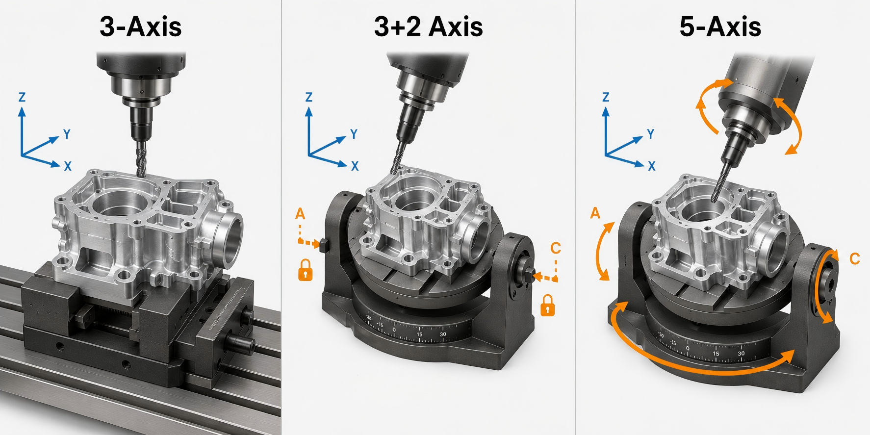
In 3+2 machining, rotary axes orient the workpiece and then remain fixed while three-axis cutting occurs. It is well suited to planes, angled faces, and holes at fixed orientations. In simultaneous 5-axis machining, linear and rotary axes move together during cutting. This is mainly used for blended surfaces, spatial profiles, and regions where the tool must continuously change orientation to maintain access or avoid interference.
Purchasing teams should compare total conforming-part cost rather than machine rate alone. Relevant items include programming and simulation, stock, fixtures, setup and alignment, cutting, tooling, first-article inspection, finishing, and rework or scrap risk. A higher machine rate may be offset when 5-axis machining completes most critical features in one primary setup and avoids several fixtures or intermediate inspections. For simple geometry, stable volume, and reusable fixtures, 3-axis may remain more economical.
When comparing quotations, ask which route is proposed; how many setups are expected; which critical features are completed together; whether dedicated fixtures are required; and whether alloy condition, finishing, first-article inspection, and quality reports are included.
5. Brightstar's Recommended Engineering and Sourcing Approach
1. Perform Feature-Based DFM Before Quotation
For custom aluminum machining projects, DFM should identify functional datums, cross-direction tolerances, inaccessible regions, excessive tool-reach risk, thin walls, small internal radii, workholding zones, and finishing interfaces. A potential 5-axis route should also be checked for rotational clearance, tool and fixture collision, stock allowance, and probing strategy. Mandatory changes should be separated from optional cost optimizations.
2. Specify Functional Results Instead of Unnecessary Process Labels
The drawing should define hole position, surface continuity, sealing function, roughness, and cosmetic acceptance instead of merely stating "5-axis required." The supplier can then select 3-axis, 3+2, or simultaneous 5-axis while remaining accountable for the result. If a customer standard, certification, or validated route explicitly requires 5-axis machining, state that requirement in the RFQ.
3. Align Inspection With the Drawing Datums
Calipers and micrometers are suitable for some dimensions, but multi-directional hole patterns, profile, true position, and relationships across faces commonly require CMM, vision measurement, or a dedicated gauge. First-article inspection should prioritize high-risk features, and roughness requirements should identify the measurement area and direction.
4. Use Prototypes and Low-Volume Production to Validate the Route
Rapid prototyping can validate workholding, distortion, burrs, finishing, inspection access, and assembly—not only external shape. After the prototype, record the material condition, setup method, program revision, critical tools, and inspection results so that low-volume production begins from a repeatable process.
6. Case Study: 5-Axis Machining of a 7075-T6 Robotic Component
This custom robotic component was machined from 7075-T6 aluminum. It features curved profiles, multiple lightweighting pockets, mounting holes, bosses, and surfaces positioned in different directions. Some critical dimensions require tolerances down to ±0.005 mm. Because substantial material had to be removed to reduce weight, maintaining rigidity and dimensional stability was an important consideration throughout machining.
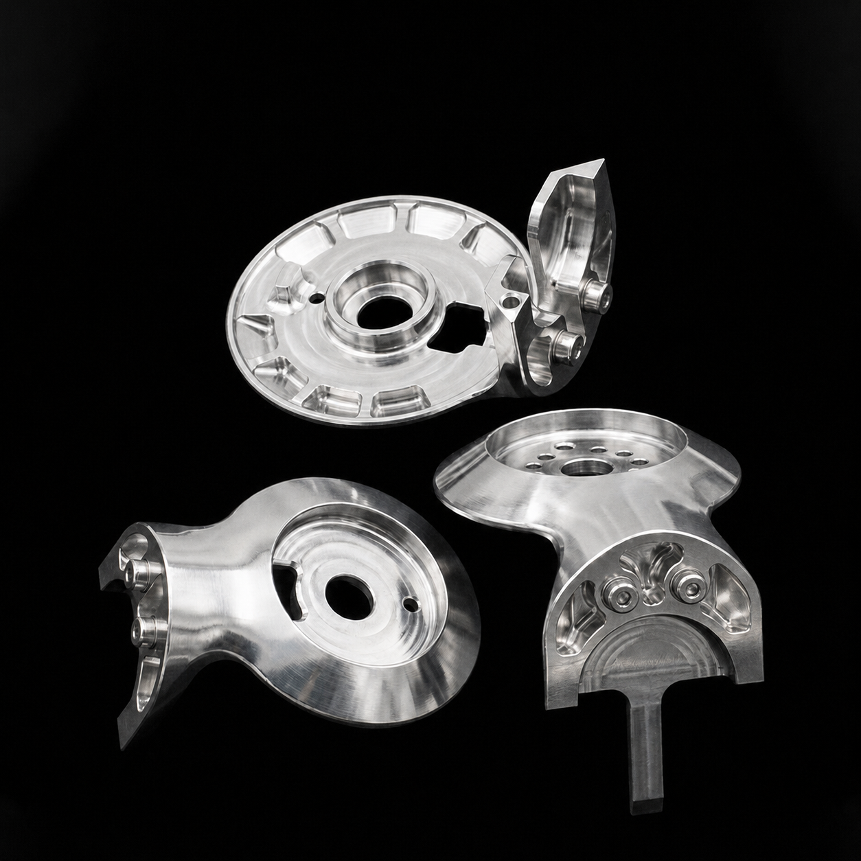
A conventional 3-axis process would have required multiple setups and repeated alignment. This could introduce datum-transfer errors between holes, bosses, and mounting surfaces machined from different directions. Some deep pockets and curved areas would also require extended tools, increasing the risk of vibration, tool deflection, and inconsistent cutter marks.
We therefore used 5-axis CNC machining to approach the side features, cavities, and complex profiles from more suitable angles. Related critical features were completed in the same primary setup wherever possible, reducing repositioning and improving consistency between machining directions.
Material removal was divided into stages. The main profile and lightweighting pockets were rough-machined first, while sufficient stock was retained on critical holes and mounting surfaces. These features were then finish-machined after the main material removal to reduce the risk of distortion in the 7075-T6 structure.
Inspection focused on critical hole diameters, positional relationships between features on different faces, mounting surfaces, bosses, and dimensional stability after the part was released from the fixture. Achieving ±0.005 mm on critical dimensions required more than a 5-axis machine: stable workholding, controlled tooling, an appropriate machining environment, and a suitable inspection method were also necessary.
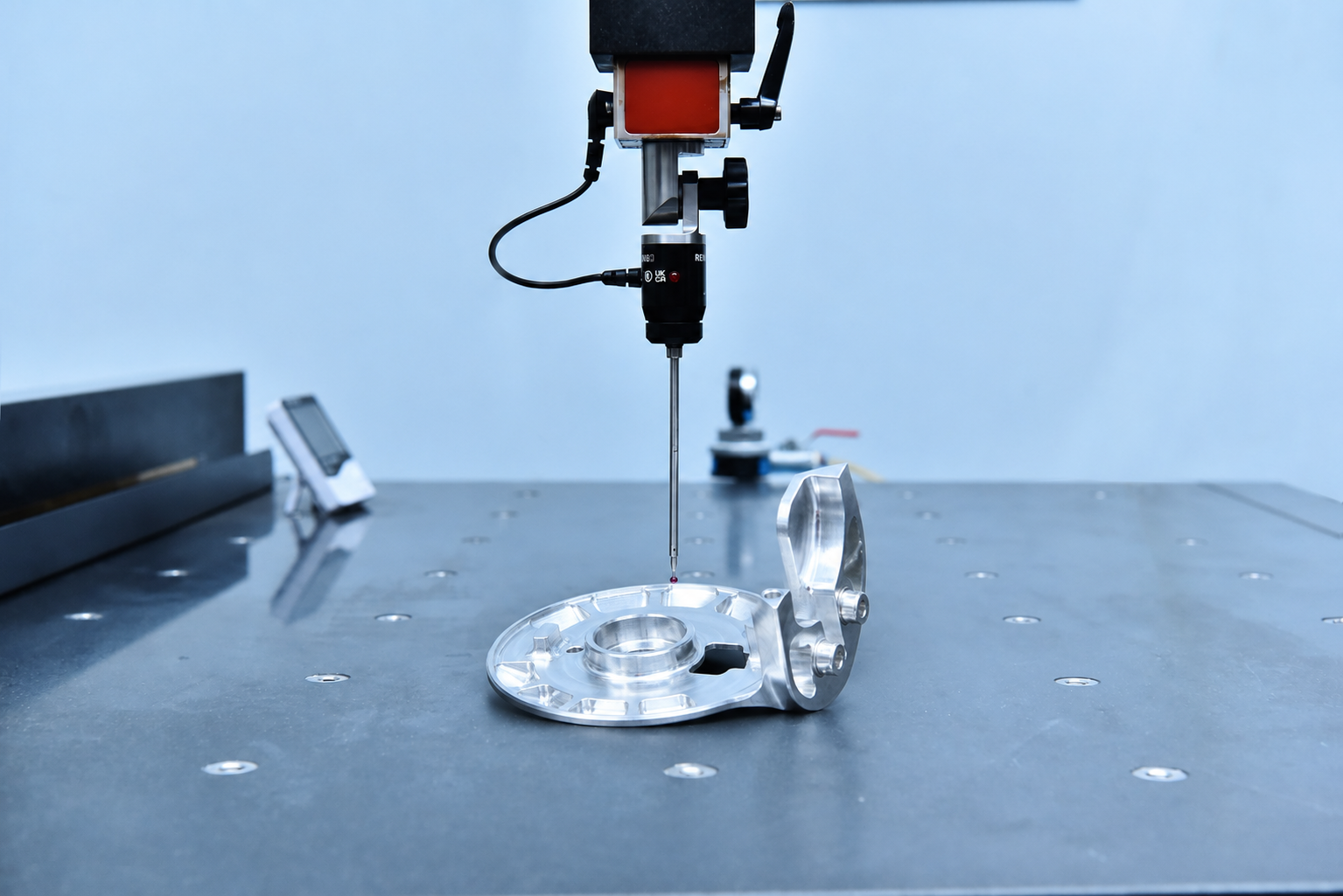
This project demonstrates that the value of 5-axis machining is not limited to producing complex shapes. It can also reduce repeated setups, improve tool access, and provide a more stable process for critical multi-directional features in lightweight robotic components.
7. Engineering and RFQ Checklist
□ Are alloy, temper, and raw-material form fully specified?
□ Are the 2D drawing and 3D model the same revision, and which controls if they conflict?
□ Does the datum system reflect assembly and function, and which features are critical?
□ Are there angled holes, undercuts, deep pockets, tall walls, small radii, or inaccessible regions?
□ Can related critical features be completed in one primary setup?
□ Do thin walls, open sections, or heavy material removal create distortion risk?
□ Is there adequate rotational clearance for the stock and fixture?
□ Are finish type, color, cosmetic areas, and masking zones defined?
□ Are dimensions accepted before or after finishing?
□ Does the RFQ include quantity, lead time, inspection reports, and packaging?
□ Does the quotation identify process, setup, inspection, and finishing assumptions?
8. Frequently Asked Questions
1. Does every multi-sided aluminum part require 5-axis machining?
No. A limited number of orthogonal faces can often be machined economically through 3-axis repositioning. Angled faces and holes at fixed orientations frequently suit 3+2. Simultaneous 5-axis becomes more valuable when critical tolerances cross several directions, a surface must be continuous, or a fixed tool direction cannot provide practical access.
2. What is the difference between 3+2 and simultaneous 5-axis machining?
In 3+2, rotary axes position the workpiece and remain fixed during three-axis cutting. In simultaneous 5-axis machining, linear and rotary axes move together during cutting to maintain changing tool orientations.
3. Does 5-axis machining automatically achieve tighter tolerances?
No. Fewer setups can shorten the datum chain, but tolerance also depends on machine condition, part stiffness, residual stress, workholding, tooling, temperature, programming, and inspection. Five-axis will not automatically solve distortion or measurement problems.
4. Are both 6061 and 7075 suitable for 5-axis machining?
Yes. Both have good machinability. Selection should follow strength, corrosion environment, availability, finishing, and cost requirements—not the number of machine axes.
5. Will 5-axis machining prevent thin-wall distortion?
Not completely. It may reduce repeated clamping, shorten tool overhang, and improve cutting direction, but residual stress, heat, clamping force, wall stiffness, and removal sequence still require control.
6. Should an RFQ specify 5-axis machining?
Specify it when a customer standard or validated process requires it. Otherwise, define functional dimensions, datums, surfaces, cosmetic acceptance, and inspection, and ask the supplier to justify the proposed route.
7. How can a buyer evaluate whether a 5-axis quotation is reasonable?
Review the included material condition, programming, fixtures, setup count, machining, inspection, and finishing. Compare total conforming-part cost and technical risk rather than machine-hour rate alone.
Conclusion
Whether a custom CNC machined aluminum parts requires 5-axis machining depends on tool access, datum relationships, setup count, continuous surfaces, part rigidity, finishing dimensions, and total project cost. A well-chosen 5-axis process can reduce repositioning and improve consistency among multi-face critical features. For straightforward parts that can be repositioned repeatably, however, 5-axis machining does not automatically add value.
Brightstar Prototype CNC Co., Ltd. provides aluminum CNC machining service and custom aluminum machining for complex custom parts and low-volume production. If you are sourcing CNC aluminum parts with multi-directional features, tight tolerances, or difficult tool access, send us your 2D drawings, 3D models, material specifications, quantities, and inspection requirements for a DFM review and quotation.
References
Haas Automation — Universal Machines:
https://www.haascnc.com/machines/vertical-mills/universal-machine.html
Haas Automation — 5-Axis Machining Simplified:
https://www.haascnc.com/productivity/5-Axis-Simplified.html
ISO — ISO 2768-1:1989, General tolerances—Part 1:
https://www.iso.org/standard/7748.html
Disclaimer
All quantitative data (percentages and hourly rates) provided in this article are for illustrative and educational purposes only, based on industry averages. Actual costs may vary depending on specific part geometry, fluctuations in raw material market prices, and regional labor rates. For accurate project costing, Brightstar Prototype CNC Co., Ltd recommends contacting our team directly for current quotes tailored to your specific requirements.